
RF Fundamentals & Optimization
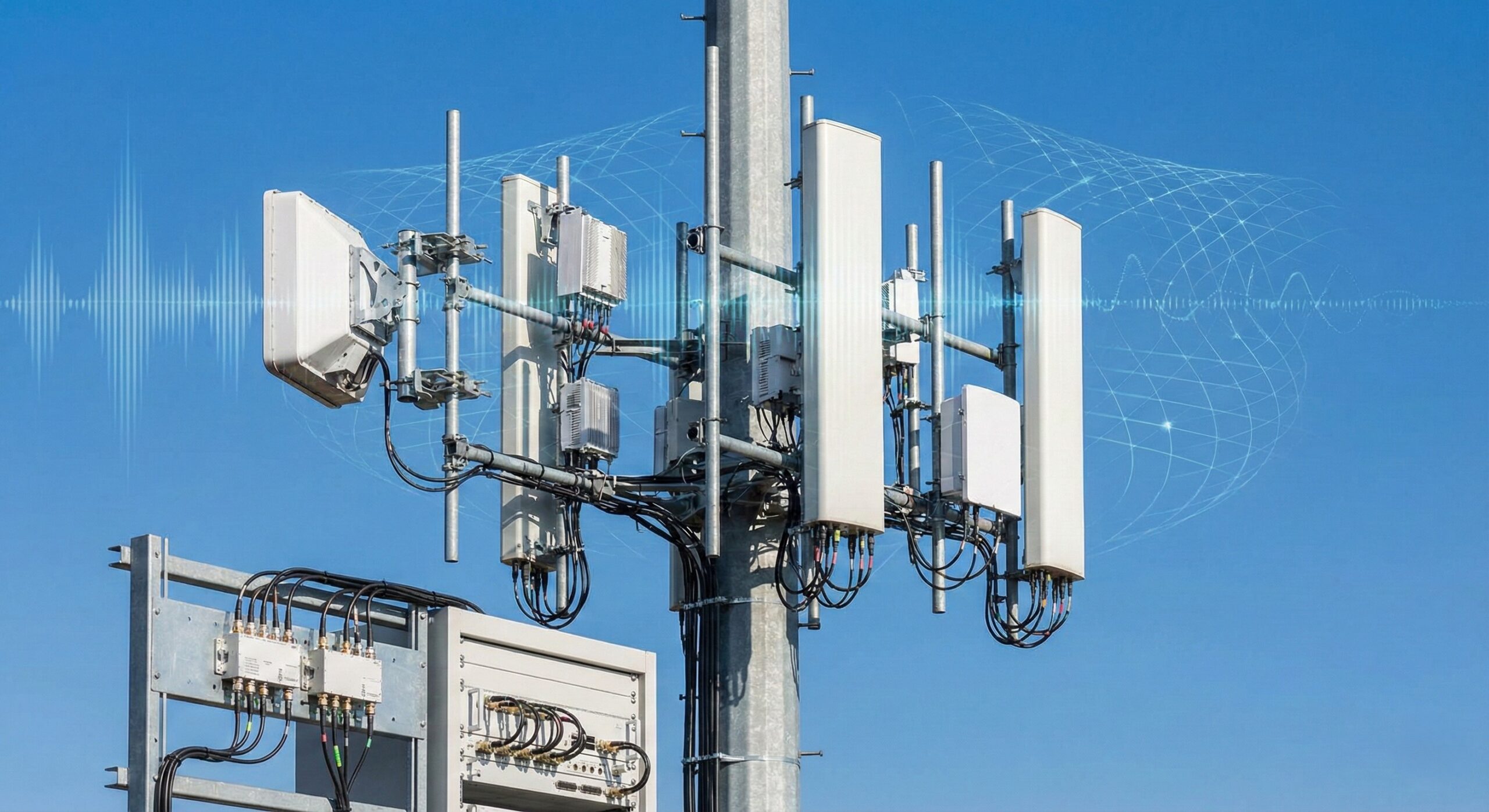
1. Antennas: How does Half-Power Beamwidth (HPBW) actually impact sector overlap? A: HPBW defines the angle where the antenna’s gain drops by 3dB from the peak. For RF planning, a narrower horizontal HPBW (e.g., 33° vs. 65°) provides higher gain and tighter sectorization, reducing co-channel interference (PCI collision) between sectors. However, if the beamwidth is too narrow for the intended coverage area, it creates “nulls” or coverage holes between sectors, requiring careful azimuth planning.
2. Tilts: What is the distinct coverage impact of Mechanical Tilt vs. Electrical Tilt? A: Electrical Tilt (e-tilt) steers the main lobe uniformly without distorting the horizontal pattern, maintaining the “peanut” shape of the coverage. It is superior for managing cell borders and interference in 4G/5G networks. Mechanical Tilt (m-tilt) physically angles the antenna face. While effective for localized footprint reduction, aggressive m-tilt can deform the pattern (blooming), causing side lobes to shoot up towards the horizon, potentially creating pilot pollution in distant cells.
3. Diplexers: Can I use a Diplexer to combine two same-band radios? A: No. A Diplexer is a frequency-selective device designed to combine or separate different frequency bands (e.g., 700MHz and 2100MHz) onto a single feeder with minimal loss. To combine two radios operating in the same band, you must use a Combiner (specifically a Hybrid Combiner), though this typically introduces a 3dB loss per channel.
4. Power: Why do we reference transmit power in dBm rather than Watts in link budgets? A: dBm (decibel-milliwatts) is logarithmic, which makes calculating link budgets significantly easier. Since gains (antennas, amplifiers) and losses (cables, connectors) are measured in dB, using dBm allows you to simply add and subtract values rather than multiplying and dividing Watts. For reference: 43 dBm = 20 Watts; 46 dBm = 40 Watts.
5. PCI: What are the primary constraints when planning Physical Cell Identities (PCI)? A: The goal is to avoid PCI Confusion (two neighbors having the same PCI) and PCI Collision (a cell and its immediate neighbor having the same PCI). Additionally, you must plan for Modulo 3 (LTE) or Modulo 4/30 (5G) conflicts. If adjacent cells share the same Reference Signal (RS) shift (determined by PCI mod 3), it significantly degrades SINR due to pilot pollution.
6. Splitters: What is the difference between a Reactive Splitter and a Resistive Splitter? A:
- Reactive Splitters (Wilkinson): Low loss/high power. They are efficient and usually used for distributing high-power signals to antennas (DAS systems) but have narrower bandwidths.
- Resistive Splitters: High loss/broadband. They use resistors to match impedance, resulting in higher insertion loss (typically 6dB for a 2-way), but they offer very wide bandwidth and excellent port-to-port isolation, making them ideal for test benches or monitoring ports.
7. RSI: Why is Root Sequence Index (RSI) planning critical for RACH performance? A: RSI is used to generate the Random Access Preambles that UEs use to initiate access to the network. If two cells with overlapping coverage use the same RSI (or RSIs with high correlation), the eNodeB/gNodeB cannot distinguish which cell the UE is trying to access. This leads to RACH failures, poor setup success rates, and handover failures.
8. Cable: How does VSWR relate to Return Loss? A: Both measure the efficiency of power transfer and signal reflection due to impedance mismatch.
- VSWR (Voltage Standing Wave Ratio): A ratio (e.g., 1.5:1). 1:1 is perfect.
- Return Loss (RL): Measured in dB. It represents how much signal is lost (not reflected) back to the source.
- Rule of Thumb: A VSWR of 1.5:1 corresponds to a Return Loss of ~14dB (acceptable). A VSWR of 1.2:1 corresponds to ~20dB (excellent).
9. Combiners: When should I use a Hybrid Combiner versus a Cavity Combiner? A:
- Cavity Combiners: Use tuned filters to combine different frequencies with very low insertion loss (<1dB). They cannot combine co-channel frequencies.
- Hybrid Combiners: Can combine any signals (even same frequency) and provide high isolation, but they inherently suffer a 3dB insertion loss (half the power is dissipated as heat). Use Hybrids only when Cavity combining is impossible (e.g., same-band combining).
10. Antenna: What is “Null Fill” and why do I need it? A: In high-gain antennas, deep nulls (signal drops) can occur between the main lobe and the first side lobe, specifically affecting users close to the tower (under the main beam). Null Fill is a design feature that electrically fills these gaps (usually to -15dB or -20dB relative to peak) to ensure continuous coverage for users in the “doughnut hole” near the site base.